- #SYSTEM VERILOG FOR PARALLEL TO SERIAL CONVERTER HOW TO#
- #SYSTEM VERILOG FOR PARALLEL TO SERIAL CONVERTER SERIAL#
Check the modified blocks with a test-bench. If the receiver de-asserts this line, the transmitter will keep (freeze) the last bit sent on the line, until the ‘receiver ready’ signal is asserted again.
#SYSTEM VERILOG FOR PARALLEL TO SERIAL CONVERTER SERIAL#
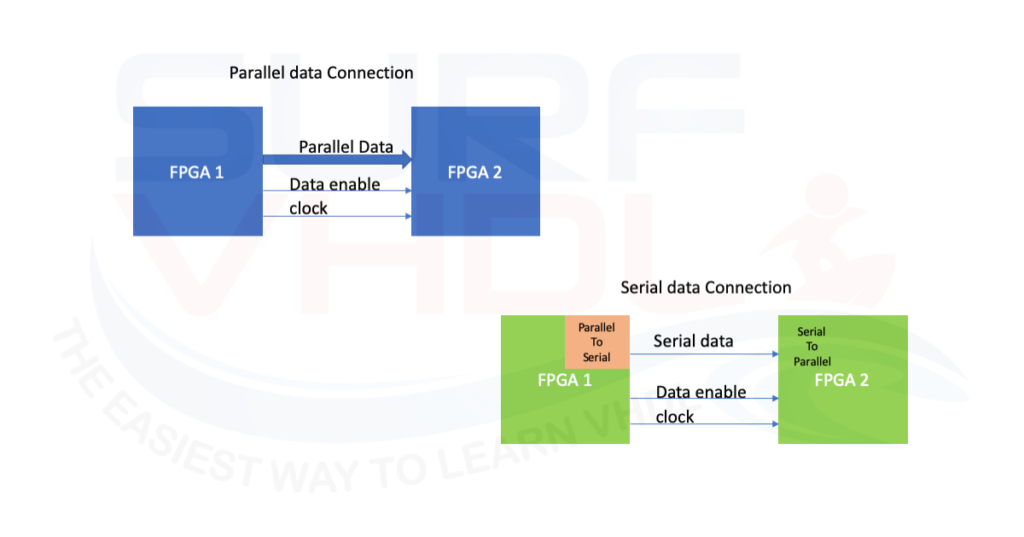
This two-step process is schematically illustrated in the accompanying figure. Parallel To Serial Converter Verilog Code For Seven 4,6/5 2580 reviews Peer Reviewed Journal. 2) What is the binary number system The system which has a base 2 is known as the binary system and it consists of only two digits 0 and 1. If the 8251A is programmed for asynchronous transmission, its framed data words must have at least one start bit, or possibly a one and a half, or two stop bits. It can also be programmed to either transmit or receive data in asynchronous or synchronous forms. Once this is achieved, with the help of the clock, data is shifted one bit a a time from the last flip-flop. This chip can be programmed to convert parallel data to serial and vice versa. Modify both blocks and test them with a modified test-bench. In this converter all parallel data is loaded (stored) simultaneously into the D-type flip-flops.

The Parallel to serial converter will sample this line and will start a new transmission only if this line is asserted. The received data is available in parallel format on the dataout bus. If a framein signal is detected, the data is latched in and the datardy output is asserted until the rd input is asserted by the host.

module trai1enc( din ,clk ,reset ,dout ) output 2:0 dout wire 2.
#SYSTEM VERILOG FOR PARALLEL TO SERIAL CONVERTER HOW TO#
How to write the code for it without the testbench to simulate,So that data (serial input) should be continuously sent (maximum up to 4 bits i want to send). The received data is available in parallel format on the data_outbus.įor the simulation, the Parallel to serial converter is used to generate data and the ser2par receives the data. I have written serial in parallel out shift register verilog code. If a frame_insignal is detected, the data is latched in and the data_rdyoutput is asserted until the rdinput is asserted by the host.

I tried the following code which works in RTL but does not verify on Cadence Conformal. This VHDL module receives serial data from the data_inline. I am looking to design a serial to parallel converter in Verilog which converts a fast clock serial input to a slower clock parallel input.


 0 kommentar(er)
